Is it mandatory to install a permanent strainer on the pump suction piping?
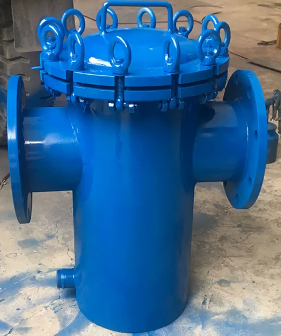
According to HG20559-1993, "Regulations for the Design of Piping and Instrumentation Diagrams (P&ID)," either a permanent or temporary pipeline strainer must be installed on the pump suction line. The effective area of a permanent strainer must be at least three times the cross-sectional area of the pipe, while that of a temporary strainer must be at least twice the area. Permanent strainers are mandatory for pumps with small internal clearances-such as screw pumps, gear pumps, plunger pumps, and piston pumps-as well as for non-metallic pumps. In systems without a standby pump, the permanent strainer arrangement must include an online spare to allow for switching during maintenance. Generally, centrifugal pumps do not require permanent pipeline strainers unless the process fluid is dirty or there are other specific process requirements. Pumps equipped with permanent strainers also require temporary strainers for the start-up phase; for small-diameter suction lines (≤DN40), permanent strainers may also be used-typically Y-type strainers, though other types may be selected based on pump characteristics and requirements (e.g., for canned motor pumps). The strainer should be installed between the pump and the suction isolation valve, with one strainer typically provided for each pump.
According to the *Industrial Pump Selection Manual* (3rd Edition, 2025), typical pump piping configurations dictate that pumps with small internal clearances-such as screw pumps, gear pumps, and plunger pumps-should be fitted with permanent strainers (one per pump, located between the isolation valve and the pump inlet). Centrifugal pumps generally do not require permanent strainers unless the fluid is dirty or specific requirements apply; however, they do require temporary strainers for start-up. For pipe diameters ≤DN40, permanent strainers (usually Y-type) may also be installed, positioned immediately downstream of the suction isolation valve.
The requirement for permanent strainers on the suction lines of small-clearance pumps (primarily positive displacement pumps) is understandable, as solid particles or rust/debris could damage gear surfaces or screws. Conversely, for centrifugal pumps, permanent strainers are generally not installed unless the fluid is dirty or special conditions exist; only temporary strainers for the start-up phase are required. While installing a filter is a sound practice, one must comprehensively analyze the consequences of failing to promptly detect filter clogging. For instance, with centrifugal pumps, the long-term accumulation of impurities leads to filter clogging and an increased pressure drop in the suction piping; this can trigger pump cavitation, which is detrimental to long-term pump operation. Two critical factors in filter selection and design are filtration area and allowable pressure drop. Standard SHT3411 specifies allowable pressure drop values for various filter types based on filtration area (these values apply to water at ambient temperature; manufacturers must perform specific pressure drop calculations when operating conditions or media properties differ).
5.6 The selection of filter mesh size should comply with the following requirements:
a) The filter mesh size should not exceed 80 mesh;
b) For media with a viscosity greater than 20 mm²/s at the operating temperature, a mesh size of 10 to 40 mesh is recommended;
c) For lubricating oils, a mesh size of 40 mesh is recommended;
d) If the pump has specific filtration precision requirements, the filter should be selected in accordance with those requirements.
5.7 The area ratio (filter area to pipe cross-sectional area) for conical filters should be 1.5 to 2 times; for Y-type and T-type filters, it should be 2 to 3 times; and for basket filters, it should be 3 to 10 times. Refer to Appendix C for pressure drop values for pump filters.
5.7 The area ratio for basket filters should be determined based on the viscosity of the medium; for high-viscosity heavy oils, a ratio of 6 to 10 times is recommended. An excessively low ratio results in a high pressure drop across the filter, thereby impairing the pump's normal operation.
|
Flow velocity (m/s) |
Multiple of effective filtration area to pipe cross-sectional area |
||||
|
2 |
3 |
4 |
5 |
10 |
|
|
0.5 |
123.4 |
54.9 |
30.9 |
19.8 |
5 |
|
0.75 |
277.7 |
123.4 |
69.4 |
44.4 |
11 |
|
1 |
493.8 |
219.4 |
123.4 |
79 |
20 |
|
1.25 |
771.5 |
342.9 |
192.9 |
123.4 |
31 |
|
1.5 |
1110.9 |
493.8 |
277.7 |
177.8 |
44 |
Relying entirely on the manufacturer for pressure drop calculations may not be appropriate; from an engineering design perspective, the maximum allowable pressure drop for the filter can be determined by calculating the Net Positive Suction Head (NPSH) available at the pump inlet under actual operating conditions, and this requirement can then be specified in the filter data sheet for verification by the manufacturer. Therefore, the focus should be on monitoring pressure drop changes across the filter during actual operation; pressure gauges or remote pressure transmitters can be installed upstream and downstream of the filter to trigger corrective measures if the differential pressure exceeds the allowable range. If the process strictly requires a filter at the pump inlet, a standby pump configuration can be adopted, allowing for periodic switching between pumps (e.g., Pump A and Pump B) to facilitate filter element cleaning or replacement without disrupting production. GB/T 3836.26, "Explosive atmospheres - Part 26: Guidance on electrostatic hazards," classifies filters as equipment capable of generating significant static electricity; different mesh sizes result in varying levels of charge accumulation, with microporous and medium-fine filters capable of generating high and moderate charge levels, respectively. This underscores the importance of monitoring filter pressure to prevent localized clogging that could cause the pressure drop to exceed allowable limits. For such filters, it is essential to consider residence time requirements under specific operating conditions and to ensure that all conductive internal components and external housing parts are equipotentially bonded and grounded.