


Applicability Conditions
For fixed-roof storage tanks that lack a frangible roof-to-shell attachment (as defined in API 650), this calculation method must be applied. If the tank design incorporates a frangible roof-to-shell attachment, no additional calculation for emergency venting during a fire is required.
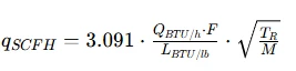
Core Formula (Equation 14, SI units; output: equivalent standard air flow rate 'q',Nm^3/h)

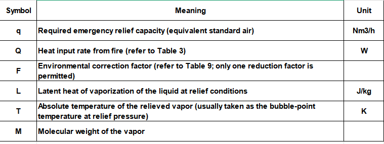
USC version (output in SCFH of air):
TR: Rankine temperature °R
Step-by-Step Algorithm Procedure (SOP)
Step 1: Determine the wetted surface area (ATWS) of the storage tank.
- Vertical cylindrical tanks: The surface area of the tank shell below the liquid level (the tank bottom is excluded from the wetted surface area).
- Horizontal tanks: The smaller of the following two values-the area calculated using a 10 ft (3.048 m) dimension along the diameter or a 30 ft (9.144 m) dimension along the length.
- Spherical tanks: The total wetted surface area.
Step 2: Determine the heat input from fire (Q, in Watts) using ATWS and Table 3.
API 2000, Table 3: Heat Load (based on an uninsulated, bare tank without firewater protection)

Step 3: Select the environmental factor F (Table 9; only one reduction factor may be applied-they cannot be combined)
- Bare tank, unprotected: (F = 1.0)
- Insulation (meeting fire integrity requirements): (F = 0.3)
- Equipped with an effective fixed fire-sprinkler system: (F = 0.3)
- Buried (earth-covered) storage tank: (F = 0.03)
⚠️ Combining insulation and sprinkler system reductions is not permitted; use the lowest applicable F value.
Step 4: Determine fluid property values
1. L: Latent heat of vaporization at the relieving pressure and temperature (not the latent heat at ambient temperature and pressure).
2. T: Bubble-point temperature of the liquid at the relieving pressure (in Kelvin).
3. M: Molecular weight of the vaporized material within the storage tank.
Step 5: Substitute into Equation (14) to calculate the equivalent air-relieving capacity, q.
Step 6: Determine the relieving device selection
The calculated value, q, represents the equivalent air capacity. The rated relieving capacity of the selected emergency relief valve, manhole, or rupture disk must be greater than or equal to this calculated value.
Note: The fire-exposure scenario defined in API 2000 is considered the single worst-case scenario; it should not be combined with normal operational flow (inlet/outlet) or thermal breathing.
Additional boundary conditions (3.3.3.3.3–3.3.3.3.7)
1. If a tank contains multiple liquids, use the fluid with the lowest latent heat of vaporization (representing the most severe scenario).
2. If the liquid will not boil under fire-exposure pressure (i.e., the pressure is significantly higher than the bubble-point pressure), this formula does not apply; a thermal expansion model must be used instead.
3. Tanks with frangible roof-to-shell joints: These are exempt from this fire-relief calculation, though they must still comply with the frangible roof construction requirements specified in API 650.
4. This calculation method applies only to atmospheric or low-pressure storage tanks (design pressure ≤ 103.4 kPag / 15 psig).
Calculation Example (SI)
Vertical tank, wetted area (ATWS = 200 m²), bare tank without protection (F = 1.0); medium: hexane (L = 334,000 J/kg, T = 342 K, M = 86.2)


