
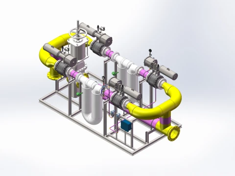
Comprehensive Structure of Jet A-1 Metering Skid
Application: Airport fuel depot truck loading / pipeline transfer custody transfer metering skids. Features include API 5L Gr.B Sch40 seamless carbon steel piping, internal FBE epoxy coating, Class 150 ANSI flanges, and full Ex d IIC T6 explosion-proof rating. The system comprises eight major modules: skid base steel structure, process piping system, filtration & purification unit, core metering unit, valve & safety shut-off unit, instrumentation & sensing system, explosion-proof electrical & automation system, and safety protection accessories; standard process flow included.
3D Model of Jet A-1 Metering Skid
On-site Skid Unit
I. Skid-Mounted Steel Base Structure (Skid Base Assembly)
1. Main Body: Welded H-beam/I-beam frame; stress-relieved via integral annealing; sandblasted and finished with anti-corrosive epoxy coating.
2. Functional Zones: Equipment support area, instrument control cabinet area, cable trays, and grounding busbar.
3. Accessories: Lifting lugs, base mounting plates, pipeline supports, explosion-proof cable trays, and grounding flat bars.
4. Process Integration: All internal piping is factory pre-fabricated and welded; includes non-destructive testing (NDT), hydrostatic and pneumatic leak testing, and comprehensive factory acceptance testing (FAT).
II. Process Piping System (Compatible with your specified 3"–16" Sch40 seamless pipe)
Piping Standards
API 5L Gr.B seamless carbon steel, Sch40 wall thickness; internal anti-static FBE or liquid epoxy coating; external 3LPE anti-corrosion coating; ends prepared with welding bevels. Elbows, tees, and reducers are long-radius (LR) seamless butt-weld fittings. Pipeline Section Breakdown
1. Inlet Header Section: Connects to the storage tank/pump house inlet header; equipped with a main shut-off gate valve, temporary sampling port, and drain/vent line.
2. Pre-filtration Section: Coarse filter and air eliminator in series to remove large particles and free air bubbles.
3. Metering Main Section: Flow meter straight pipe section (10D upstream and 5D downstream straight pipe runs for flow stabilization to ensure metering accuracy).
4. Automatic Valve Assembly Section: Electric/pneumatic shut-off valves, check valves, pressure relief bypass, and recirculation line.
5. Outlet Transfer Section: Connects to the loading arm/apron fuel pipeline; includes a blind flange access point for maintenance.
6. Auxiliary Piping: Drain lines, vent lines, pressure-balancing recirculation line, and calibration/verification bypass (interface for standard prover verification).
III. Filtration and Purification Unit (Forced oil-water separation for aviation fuel, meeting civil aviation fuel standards)
1. Coarse Filter (Upstream protection): 20μm filtration rating, stainless steel basket-type element; protects downstream flow meters and precision separators; equipped with a differential pressure transmitter that triggers an alarm for element replacement when limits are exceeded.
2. Air Eliminator (Core air bubble removal): Centrifugal automatic venting to separate entrained air from fuel; equipped with an SME bubble sensor that automatically interlocks to reduce flow upon gas detection, preventing metering errors caused by gas.
3. Filter-Separator (Critical equipment for aviation fuel): First-stage coalescing element (water separation) + second-stage separation element (impurity capture); water sump equipped with a liquid level alarm; outlet fuel cleanliness meets Aviation Kerosene Class 1 standards; equipped with an outlet fuel sampling valve.
IV. Core Metering Unit (Custody transfer grade; certified by civil aviation MID/Metrology Institute)
Two mainstream metering configurations
Option 1: Coriolis Mass Flow Meter (Preferred choice for high-accuracy custody transfer)
1. Coriolis mass flow meter unit (316L liner, anti-static)
2. Flow transmitter: Directly outputs mass flow rate, temperature, and density; performs automatic calculations. Standard volume at 20°C; no manual compensation required
3. Ancillary equipment: Flow computer (batch controller), pulse signal output, local LCD display
Option 2: Turbine flow meter (for high-flow pipeline transfer)
1. High-precision turbine flow meter with pulse generator; accuracy: ±0.2%
2. PT100 temperature transmitter and pressure transmitter; inputs to flow computer for temperature, pressure, and density compensation
3. Standard calibration bypass (interface for pipe prover/standard metal measure vessel for periodic online calibration)
V. Valve manifold safety shut-off unit (explosion-proof electric valves; matching the Class 150 flanged ball/gate/check valves mentioned earlier)
1. Manual main gate valve: For isolation during maintenance; includes long-radius (LR) 90° welded elbow
2. Explosion-proof electric shut-off ball valve (main loading valve): Automatic open/close for batch operations; interlocked with soft-start oil pump
3. Emergency shut-off valve (ESD fusible link valve): Automatic shut-off via fusible link triggered by high fire temperatures; highest-level safety interlock
4. Non-return (check) valve: Prevents backflow; protects flow meter and filter-separator
5. Pressure relief bypass valve: Automatic relief upon overpressure; protects pipeline and metering equipment
6. Deadman manual control valve: For on-site emergency manual pump stop and valve closure; automatic fuel cut-off when operator leaves
7. Vent/drain ball valve: For depressurization and drainage during maintenance
VI. Instrumentation and sensing system (explosion-proof/intrinsically safe; includes interlock logic)
1. Pressure detection
1. Inlet electric contact pressure gauge (for low-pressure/oil-loss interlock requirement): Stops pump and closes valve immediately if oil pressure drops below setpoint
2. Inlet/outlet pressure transmitters: Real-time remote monitoring of pipeline pressure; overpressure alarm
2. Temperature detection: PT100 Platinum resistance temperature sensor; supports metering compensation and low-temperature freeze protection alarms.
3. Differential pressure instruments: Monitors differential pressure across filters and filter-separators; provides early warning for filter element clogging.
4. Liquid level detection: Water accumulation level switch for filter-separators; interlock to stop the pump if water accumulation exceeds limits.
5. Static grounding monitor: Prevents pump startup if not grounded during loading; monitors static elimination status.
6. Overfill prevention probe: Interlock to cut off the oil supply if the tank overflows.
7. Combustible gas detector: Audible and visual alarms for excessive hydrocarbon concentration within the skid; linked to ESD (Emergency Shutdown) system for cutoff.
VII. Explosion-proof electrical and automatic control systems (configured with 11kW oil pump soft-start control logic)
1. Explosion-proof power distribution cabinet
Three-phase 380V main circuit breaker; 11kW explosion-proof soft starter for the oil pump (ensures smooth startup).
Power supply circuits for electric valve actuators; motor overload and phase-loss protection.
Enclosures rated Ex d IIC T6 (explosion-proof); cable entries sealed with explosion-proof glands.
2. Explosion-proof control cabinet (PLC-based batch control unit)
1. Core batch controller/PLC: Preset quantitative dispensing; automatic start/stop logic.
2. Control logic (fully compliant with your requirements)
o Startup: Soft-start activates the oil pump → Automatic opening of the electric outlet valve.
o Normal shutdown: Close electric valve → Delayed pump shutdown.
o Low-pressure/oil-starvation interlock (via electric contact pressure gauge): Simultaneous pump shutdown, valve closure, and latched audible/visual alarm.
3. Operating components: Explosion-proof local start/stop buttons, emergency stop button, fault reset button, and status indicator lights.
4. Outputs: Explosion-proof audible/visual alarm, local LCD operation screen, and ticket printer.
5. Communication: Modbus RS485; interfaces with the oil depot DCS/management system to upload cumulative dispensing volume and fault records.
3. Explosion-proof wiring and grounding systems
Cables for all instruments, valves, and motors (intrinsically safe) routed through explosion-proof galvanized steel conduit
Integrated equipotential static grounding for the skid structure, piping, equipment, and valves; grounding resistance < 4Ω
VIII. Safety protection auxiliary systems (mandatory safety facilities for aviation fuel skids)
1.Static grounding reels and anti-static bonding jumpers (copper bonding straps across all flanges and fittings)
2.Explosion-proof emergency lighting and maintenance power outlets
3.Fire containment bund, oil-water separator/collection pit, and dry powder fire extinguishing system
4.Lightning protection grounding system; skid structure connected to the plant's lightning protection grid
5.Blind flanges, identification tags, flow direction markers, and explosion-proof warning signs
6.Low-temperature heat tracing (optional for northern regions): Explosion-proof electric heat tracing for freeze protection of piping and instruments
IX. Standard comprehensive process flow (top to bottom)
Inlet from storage tank → Manual gate valve → Coarse strainer → Air eliminator (bubble removal) → Filter-separator (water and impurity removal) → Temperature and pressure sensors → Flow-stabilizing straight pipe section → Coriolis / Turbine flow meter → Electric main shut-off ball valve → Outlet for loading / transfer pipeline
Interlock protection branches
1.Low-pressure protection: Loss of pressure at suction inlet (detected by electric contact pressure gauge) → ESD circuit triggers shutdown (pump stop + valve closure + alarm)
2.Over-pressure protection: Pipeline over-pressure → Pressure relief bypass opens; shutdown triggered if pressure remains excessive
3.Water accumulation / Filter element blockage: Water accumulation in separator or high differential pressure across filter → Pre-alarm → Shutdown upon exceeding limits
4.Spill / Grounding failure / Combustible gas excess: Simultaneous fuel line cutoff, pump stop, and self-locking audible-visual alarm
X. Auxiliary fittings and valves (corresponding to preliminary Bill of Materials)
1.Piping: NPS 3"–16", Sch 40, API 5L Gr. B seamless pipe; internal FBE (Fusion Bonded Epoxy) coating
2.Fittings: 90° Long Radius (LR) Long-radius butt-weld elbows, equal tees, concentric reducers, pipe caps
3. Flanges: ASME B16.5 Class 150 WN-RF (Weld Neck, Raised Face) flanges
4. Valves: Class 150 ANSI-standard gate valves, ball valves, and swing check valves (with explosion-proof electric actuators)
5. Power unit: 11 kW, 380 V explosion-proof oil pump + explosion-proof soft-start control cabinet


