YQB Series LPG Pump Operating Instructions
I. Product Overview
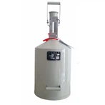
The YQB series consists of positive-displacement sliding-vane pumps designed specifically for transferring volatile, flammable, and explosive liquids such as LPG, propylene, liquid ammonia, and dimethyl ether. They are widely used in applications including LPG tanker loading/unloading, cylinder filling, tank-to-tank transfer, and workshop supply.
Model Designation

YQB: LPG Pump
Numbers (e.g., YQB35-5): Rated Flow Rate (m³/h) - Rated Differential Pressure (kgf/cm²)
Structural Features
Stator features a compound curve; rotor equipped with sliding vanes, forming 10 sealed chambers.
Mechanical seals plus O-rings at both ends ensure zero leakage and low-temperature resistance.
Built-in safety valve provides automatic recirculation protection against overpressure.
Explosion-proof motor suitable for hazardous areas; belt or coupling drive.
II. Technical Parameters (Typical)
Table
Model Flow Rate (m³/h) Speed (rpm) Differential Pressure (MPa) Inlet/Outlet (DN) Power (kW)
YQB20-5 20 780 0.5 50/40 7.5
YQB35-5 35 780 0.5 65/50 11
YQB40-6 40 600 0.6 80/65 15
YQB60-6 60 780 0.6 80/65 18.5
III. Installation Requirements
1. Piping Configuration
Inlet: Install a 30–40 mesh copper wire strainer (flow area ≥ 1.5 times the inlet pipe area) to prevent debris from entering the pump.
Outlet: Must connect a recirculation line (safety valve return to storage tank); operation with the outlet completely shut off is strictly prohibited.
Flexible Connection: Use 1–2m oil-resistant rubber hoses at the pump inlet and outlet to dampen vibration and prevent cracking.
Pipe Diameter: Inlet pipe diameter must be ≥ pump inlet diameter to prevent cavitation. 2. Safety and Foundation
Ensure reliable grounding and explosion-proof wiring for the pump and motor.
The foundation must be level and secure to prevent resonance.
Ensure a well-ventilated environment; prohibit open flames; implement anti-static measures; install a combustible gas alarm.
IV. Operating Procedures
(I) Pre-start Checks (Mandatory)
Manually rotate the shaft (via pulley/coupling) at least 2 full turns; ensure there is no binding or abnormal noise.
Verify correct rotation direction (indicated by the arrow on the pump body; clockwise when viewed from the motor end).
Fully open the inlet and recirculation valves; slightly open the outlet valve; purge air from the pump and piping (required for initial startup or after prolonged shutdown).
Check that pressure gauges and safety valves are intact and free of leaks.
(II) Startup
Jog the motor to confirm correct rotation and the absence of abnormalities.
Slowly open the outlet valve and gradually increase the load to the rated pressure (≤0.5–0.6 MPa).
Monitor for: stable pressure, minimal vibration, no leaks, and no abnormal noise.
(III) Operational Monitoring
Pressure: Inlet-outlet differential pressure **≤0.49 MPa (5 kgf/cm²)**.
Temperature: Pump body ≤60°C; ensure no overheating of the mechanical seal.
Strictly prohibit dry running, cavitation (pumping air/gas), or reverse rotation; shut down immediately for inspection if no liquid flows from the outlet.
Cylinder Transfer: Invert the cylinder (outlet positioned higher than the pump); pressure approx. 0.2 MPa; stop once the tank is full.
(IV) Shutdown
Close the outlet valve first, then fully open the recirculation valve.
Cut off the power supply; do not perform an emergency stop while the system is under pressure.
Close the inlet valve; drain residual liquid from the pump if it will be out of service for an extended period.
V. Safety Precautions (Key Points)
Explosion-proof & Fire Safety: Prohibit open flames and static electricity in the area; use explosion-proof tools and ensure reliable grounding.
Prevent Dry Running/Cavitation: Dry running for 30 seconds can destroy the seal; cavitation can damage the impeller.
Recirculation Line Required: Operation is strictly prohibited without a recirculation line; the safety valve automatically opens the recirculation path during overpressure.
Prevent Dry Friction on Mechanical Seal: Fill with liquid and vent air before startup; shut down immediately for maintenance if leakage occurs. Winter Freeze Protection: Drain residual liquid when out of service; do not use cylinders containing water in winter to prevent ice blockages.
VI. Maintenance
1. Daily (per shift)
Check pressure, vibration, leakage, and temperature.
Clean filters to prevent clogging.
2. Periodic (monthly/quarterly)
Lubrication: Apply low-temperature grease to bearings; ensure proper belt tension and check for cracks.
Seals: Mechanical seal leakage must be ≤1 drop/minute; replace if it exceeds this limit.
Safety Valve: Verify opening pressure (0.5–0.6 MPa).
3. Long-term Shutdown
Drain residual liquid and purge with nitrogen for protection; store in a dry, well-ventilated area.
VII. Common Faults and Troubleshooting
Table
Fault Symptom Possible Cause Remedy
No liquid output / Low flow Air in pump, inlet blockage, reverse rotation, cavitation Vent air, clean filter, adjust rotation, replenish liquid
Excessive pressure Outlet blockage, recirculation valve closed, safety valve stuck Clear outlet, open recirculation valve, service safety valve
Vibration / Abnormal noise Loose foundation, belt too tight, damaged bearing, cavitation Tighten foundation, adjust belt, replace bearing, prevent cavitation
Mechanical seal leakage Dry running, wear, damaged O-ring Fill with liquid, replace seal, replace O-ring
VIII. Special Warnings
This is a positive displacement pump; strictly prohibit operation with the outlet fully closed; the recirculation line is critical.
LPG is flammable and explosive; strictly prohibit open flames, prevent static electricity, and ensure ventilation during all operations.
Before maintenance, disconnect power, depressurize, drain residual liquid, and purge with nitrogen to prevent explosion or poisoning.